Indirect Object-To-Robot Pose Estimation From An External Monocular RGB Camera
Posted on
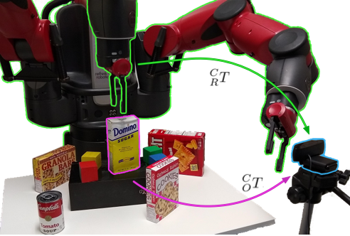
System Overview
Abstract
They present a robotic grasping system that uses a single external monocular RGB camera’s input.
The object-to-robot pose is computed upon merging the output of two neural networks: one for calculating the object-to-camera pose, and another for calculating the robot-to-camera pose.
Both these networks are trained entirely on synthetic data, relying on domain randomization to bridge the sim-to-real gap.
The latter network performs online camera calibration, the camera can be moved freely during execution without affecting the quality of the grasp.
They also present results on a new set of 28 textured household toy grocery objects, which have been selected to be made more accessible to other researchers.
In addition, to aid reproducibility of the research, they offer 3D scanned textured models, along with pre-trained weights for pose estimation.
The original paper can be found here. Moreover, code and new dataset can be found here.
Here’s a short video by the author demonstrating how this works:
Authors:
Jonathan Tremblay, Stephen Tyree, Terry Mosier, Stan Birchfield
Introduction & Related Work:
Can we use only a single monocular RGB camera and make a robot grasp objects? The researchers at NVIDIA have done just that. In a nutshell, this is how it is done:
We need to find in the camera frame where the object is.
We also need to find in the camera frame where the robot is.
Using both the above information, it is possible to find the transformations between the camera frame and robot frame, and thus determine where the object is in the robot’s frame.
Traditionally you need to keep the camera rigidly fixed and even slight variations in position could severely affect the robot’s ability to pick and place an object. However, in this work, the calibration is happening all the time which allows you to pick up the camera and move it around, and the robot will still pick up the objects correctly!
To put into context how difficult this is, recollect when you started wearing glasses for the first time, and it took you some time to understand how far objects really are than how they appear, and adjust your hand-eye coordination accordingly.
Pose estimation can be done with different setups such as with an RGB-D camera mounted external to the robot.
It can also be performed with an RGB-D camera mounted on the robot’s wrist.
Check out our research simplified post on the state-of-the-art algorithm PVN3D to see exactly how this is done!
Other notable algorithms that use RGB-D images for pose estimation include DenseFusion (CVPR, 2019) and KPAM (ISRR, 2019).
The AVID (2019) algorithm uses reinforcement learning to learn policies that are conditioned on the position of the camera. So with every changing position of the camera, the policy has to be re-learned for pose estimation to be effective.
The main contributions the researchers are making with this work are as follows:
Estimating the pose of known objects in robot’s coordinate system using an external monocular camera with real-time online calibration allowing the camera to be moved around during the experiment.
Achieved an accuracy of ~2 cm in positioning.
Due to the constraints in obtaining objects present in the YCB dataset, they have also contributed a novel set of 28 toy and grocery objects with their 3D scanned textured models and pre-trained pose-estimation weights.
System Overview
An image comes into the system where both the robot and the object are visible.
DOPE: Framework used to find the pose of the object, which is then passed to another algorithm called SimTrack to refine the pose.
Deep Object Pose Estimation (DOPE)
DOPE is the part of the system that predicts the object pose with respect to the camera’s frame of reference.
It works as follows:
Cuboid Key-point detection: First find key points that form a cuboid around each object in the scene.
Since they know what the objects look like beforehand (its color, shape, size etc. using 3D mesh files), using an algorithm called PnP, they re-project the 2D key points into 3D.
The result of PnP gives the pose of the object.
The pose detectors were trained purely on synthetic data.
The output of DOPE (i.e., the pose) is then fed into SIMTRACK for pose refinement.
SIMTRACK: Pose Refinement
SIMTRACK is takes the pose given by DOPE and refines it. It works as follows:
It first identifies swift key points from a textured objects.
It tracks the textures that it sees in the image to refine the object poses.
DREAM: Robot Pose Estimation
This framework is used to compute the pose of the robot and works in a similar way to DOPE. The steps are as follows:
The first step is to define key points on the robot, which are known to us with respect to the base of the robot.
Train a neural network to detect these key points using PnP, because just like the objects we know the geometry and pose of the robot.
Just like DOPE, this neural network is also fully trained on synthetic data of the robot.
Pose Filtering
All the various frameworks we used (DOPE, SIMTRACK, DREAM) to generate poses need to be filtered out because they may be subjected to errors and false positives.
They used a weighted moving average to ensure that these variations are smoothed out.
HOPE Objects
The research group is also introducing a set of 28 new objects for pose estimation research.
The need for doing this is because objects in the YCB datasets may not be easily available. You can find the objects here and the pre-trained weights for these objects here.
Experiments
The experiment setup consisted of :
Baxter Robot by Rethink Robotics
Titan XP GPU
Single RGB Camera – Logitech c920
YCB Objects
The experiments conducted focused on two aspects:
Positioning accuracy experiment: The goal was to make a Baxter robot’s gripper continuously track an object. This was done by attaching some weight to the middle of the Robot’s gripper, and the goal was to stabilize this weight above the object. They then measure the distance between the center of the object to where the pendulum stabilizes. This provides an accuracy for a top grasp. This experiment was performed on 5 YCB objects. For a successful grasp using the Baxter robot, the tolerance in accuracy is about 2 cm, and most trials achieve this threshold. It was observed that for very long objects (such as a long spaghetti box), the pose estimation was not very good.
Camera motion experiment: The camera was freely moved around and an analysis of the various errors observed in position along various axes during this process was measured. The distance from the robot base to the camera was varied and measured across seven instances from 1m to 1.6 m. The same positioning accuracy procedure was carried out when the camera was placed at different distances from the robot base. However, in addition to placing the camera at various positions, the camera was moved around about 30 cm (left/right/up/down) while the robot gripper was trying to stabilize the pendulum over the objects. The errors measured were within the 2 cm threshold for successful grasping by Baxter’s gripper. Ideally, the errors need to be zero – but there are some discrepancies in position and hence scope for future work to reduce these errors.
Conclusion
A robotic system capable of estimating the pose of known objects in robot’s coordinate system using an external monocular RGB camera with online calibration is performed.
The system achieves a positioning accuracy of ~2 cm.
They also contributed a novel set of 28 toy and grocery objects due to the inherent difficulty in obtaining YCB objects for researchers. To aid reproducibility, they also provide the 3D scanned textured models and pre-trained pose-estimation weights for these new objects.
The system also allows the camera to be moved freely during task execution with greater robustness.